
Quick Start
Here we set up ELCOVISION 10 ELTheo and demonstrate the basic functions such as stationing and measuring points in a CAD drawing.
First install ELTheo and register the CAD plugins.
Setting up Communication with the Theodolite
Connect the theodolite to the computer using a serial cable or wireless data or Bluetooth.
Theodolite driver
Start ElTheo and go to the Settings page:
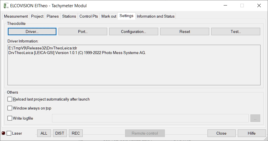
Use the Driver... button to select the communication driver for your theodolite. These can be found in the installation directory of ELTheo, the file dialogue is automatically in this directory. The following are currently available for selection:
DrvTheoLeica.tdr
Drivers for the Leica TCR Thedolite and Theodolite from other manufacturers that support the GSI8 or GSI16 protocol.
DrvTheoLeicaGeoCOM.tdr
Drivers for the Leica 11xx and 12xx Thedolites supporting a mixed GeoCom and GSI protocol.
DrvTheoTopcon.tdr
Driver for Topcon Theodolite.
DrvTheoTrimble.tdr
Driver for Trimble Theodolite.
DrvTheoTrimbleGeodimeter.tdr
Driver for GeodimeterTheodolite.
Set up Serial Interface
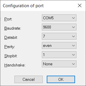
If the theodolite is connected via Bluetooth using Windows Bluetooth Manager, only the correct virtual serial port must be set, the values for speed, data bits etc. are not relevant. If no serial interface is available, check in the device manager whether one is available: Most likely there is a driver problem which must be fixed first.
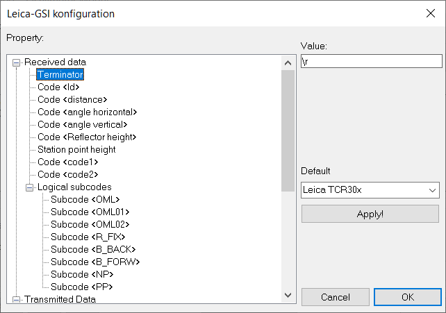
Set up theodolite device parameters
With Configuration... the instrument parameters for the thedolite are set. For most instruments, the usual factory settings are preset in the driver. If a driver supports several different instruments, these can be selected and adopted in a selection box:
Testing the Connection to the Theodolite
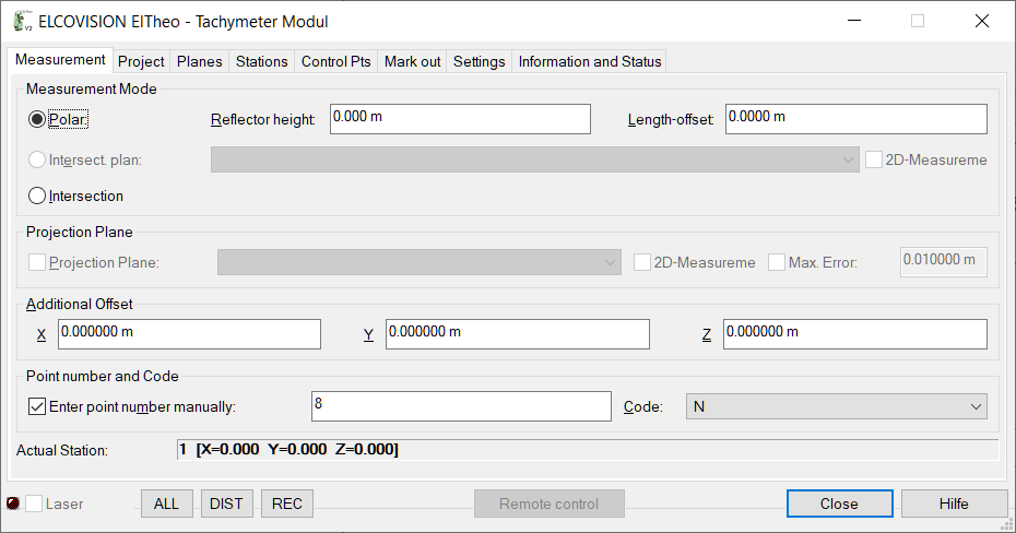
Click on Test.... The following dialogue appears:

Click on ALL and a measurement should now be triggered at the theodolite. In the upper terminal area you can see in green what was sent to the theodolite. If the measurement was successfully triggered, the response is also shown in the terminal area, and the interpreted data are in the list:
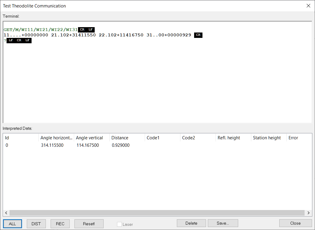
ASCII control characters in the range 0x00 to 0x1F are represented by the black background abbreviations.
If no data transmission takes place or if confused characters and number sequences are displayed, check whether the same interface parameters are really set in the theodolite and under Connection... and repeat this test.
Now trigger a measurement on the theodolite. There must be a data transmission. If not, check whether the correct line terminator character is entered in Connection....
Setting up and Orienting the Theodolite
Various methods are available for orientation. Usually a local coordinate system is defined with the first point of view. Normally the X axis is placed along a façade by means of 2 measurements:
Switch to the Stations page:
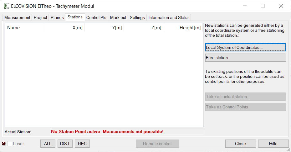
Defining a Local System of Coordinates
With Local System of Coordinates... the assistant for orientation by means of a local coordinate system is started:
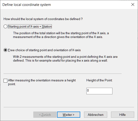
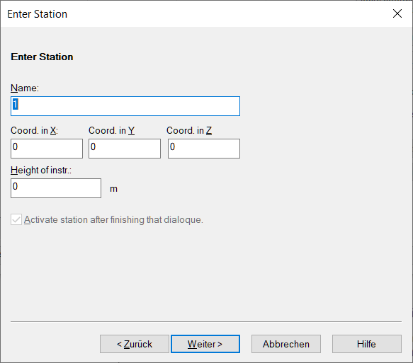
The mode for measuring an X axis is preset. Press [Next>]. On the following page you can optionally enter the coordinates of the theodolite position and the position name, if the position is to be reused later for an orientation you can enter an instrument height:
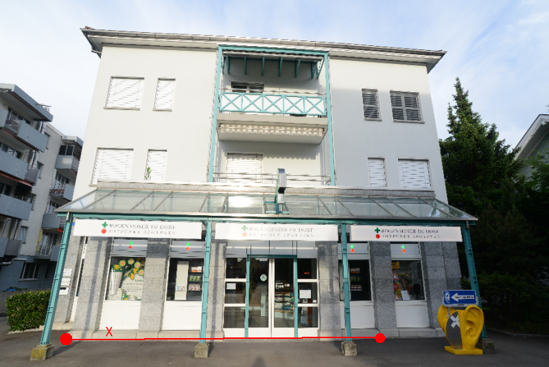
Press Next >. Now both points are measured, the point that is to be measured blinks:
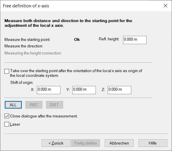
The measurements can be triggered either on the theodolite or via the ALL button in the assistant.
After measuring the 2nd point of the axis, the dialogue is automatically closed and the position is active. From now on, measurements can be made:
Drawing with Theodolite Measurements
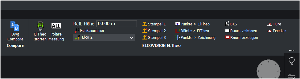
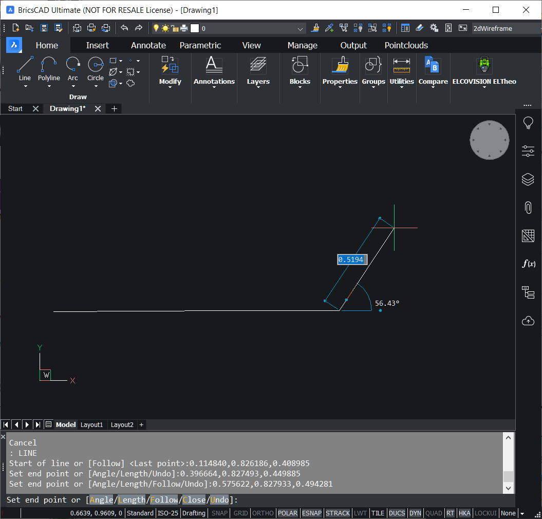
Start an AutoCAD or BricsCAD supported by ELTHeo. After creating a new drawing or loading an existing one, you can start the plugin by entering "Eltheo" in the command line. The plugin automatically connects to the ELTheo, a ribbon or toolbar is displayed in the CAD:
Start a drawing command in the CAD, e.g. line. When measurements are triggered via the All button in the ELTheo or CAD plugin or on the instrument, the measured points are transferred to the command line and the line is drawn accordingly:
Free Stationing
A theodoliot can be placed on any position and oriented by measuring at least 2 previously measured points.
All points measured are automatically logged in the Control Points page and can be viewed as a list or graph:
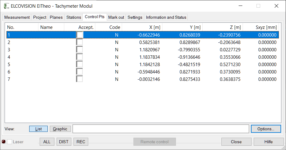

Free stationing is started in the Stations page with the command Free Station....
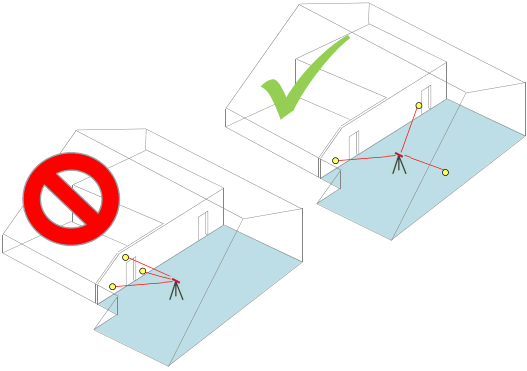
Afterwards it is advisable to switch to the page Control Points and to select those points which are to be measured in the free stationing by ticking "Accept". These points should be spatially well distributed and also in different directions:
If you arrange the main window and the free stationing dialogue as shown below, you can easily switch points off/on:
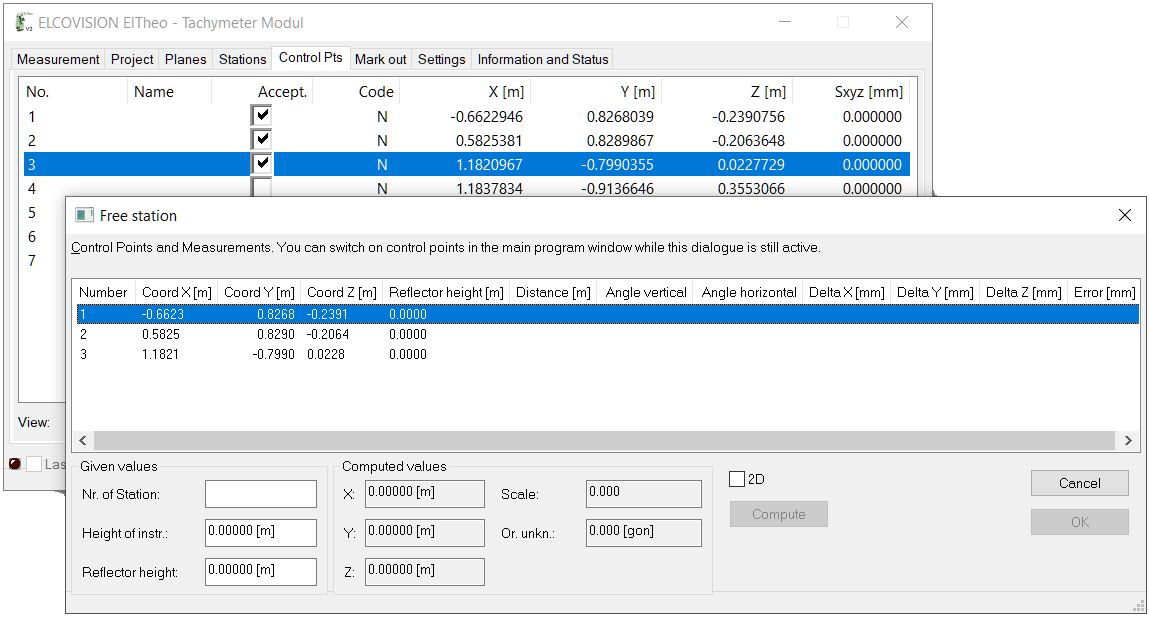
The first point in the list is automatically selected, these points must now be measured in the order shown, the remaining gap should be less than 1-2mm:
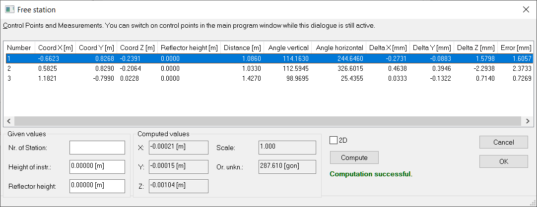
Incorrectly measured points can be re-measured as often as desired by selecting the point in the list.
If the calculation is successful, the new standpoint becomes active when the dialogue is closed with OK, and further measurements can be made from the new standpoint.
Using Points from the Drawing

Points in the drawing can now be picked and immediately transferred to the list of points to be measured and can be used normally for free stationing.